
For a while now I've been obsessed with bicycle hub dynamos. Two of my three bikes are equipped with them. I ride quite a lot at night around the streets of Toronto, and for almost half of my year-round commute I ride home from work in the dark. A well designed dynamo-powered bicycle lighting system can provide a surprising amount of light with very little load on the rider and almost no extra drag while riding during the day with the lights off.
I bought my wife a very dilapidated 1966 Raleigh Superbe from a friendly street bike peddler with an enthusiasm for old English 3 speeds. The Superbe was the high-end model of the Raleigh 3 speed family and came equipped with a Sturmey-Archer GH6 6V 2W (some sources say 3W) Dynohub and a shiny chrome light set (unfortunately missing from this example).
I overhauled the Dynohub and was excited to find out that it still worked. After some hunting around on ebay I got lucky and managed to track down a NOS Sturmey Archer chrome light set for a reasonable price (some folks are willing to pay over $100 for a used set!).
 Brand new out of the box (hand courtesy of the gentlemen who got far less than 100 bux for his shiny wares).
The original configuration did not throw out much light at low speeds and, of course, the lights went out completely when the bicycle came to a stop. A few modern dynamo lights have a supercapacitor that can power a small auxiliary LED while the bike is stationary (called a standlight). Busch & Muller even make a nice chrome retro-styled headlight with this feature but offer no matching rear light. I have one of these for my bike equipped with a modern 3W Shimano hub, but the old GH6 doesn't quite put out enough juice to satisfactorily light up the 2.4W halogen bulb. Being an obsessive weirdo this just wouldn't do, so I thought I'd try to build a modern dynamo lighting system with a standlight into the original Sturmey Archer lamps for my wife's Raleigh.
Step One: Finding Suitable LEDs
The GH6 has a lower output than modern dynamos, so using LEDs as the main lamps instead of the original incandescent bulbs makes good sense to get high brightness at low speeds. With a total power output of about 2W, I figured 1W front and rear should do. Bicycle dynamos put out AC, so an AC to DC conversion needs to be worked out as well - more on that later...
Scrounging around google, I found that there are several manufacturers that make drop-in LED replacements for flashlight bulbs. The TLE-1S is a 1W white LED with a screw base that fits the Sturmey Archer head lamp. $15.99 for a flashlight bulb? Only a crazy person would want this. They do brag about a 'power push' circuit which is supposed to suck every last drop of juice out of the batteries that are meant to power it without dimming. Most importantly, it accepts a fairly wide input voltage (3-9V) and presumably has some way of limiting the current going into the LED.
Finding an appropriate taillight proved more difficult. The Sturmey Archer tail lamp uses a bulb with an old fashioned automotive wedge base. There are LED replacement bulbs available in a rainbow of colours, but they all seem to be 12V only. I experimented with a mini maglight replacement bulb that used pin contacts and soldered them to the filament terminals of a broken wedge bulb base and then encased the whole thing in silicone, but unlike the TLE-1S the TLE-20 didn't seem to have suitable current limiting circuitry. Unfortunately it took blowing two $12 bulbs to learn this. bummer. :(
I finally settled on a 2V 350mA 1W jumbo red LED from digikey, but it's a bit steep at $5.17. This is just a LED so it will need a current limiting resistor.
Step Two: Designing a standlight
Many modern dynamo bicycle lights use a supercapacitor to power auxiliary low power LEDs, which provide some light while the bicycle is stationary. I only wanted to work with the main bulbs in the front and rear lamps and keeping 2W worth of LEDs lit for more than a few seconds would require some hefty supercapacitors. I originally tried to work out a design using a 120F supercapacitor, which is slightly shorter and fatter than an AA battery. The supercapacitor solution seems the most elegant, but with a typical supercapacitor rating of only 2.3V and the dynamo's output ranging from 3-20 VDC (after running it through a bridge rectifier) the design requirements quickly exceeded my ability.
Using a battery to power the LEDs and using the dynohub to recharge the battery seemed like a less elegant but more practical solution to keeping the lights on when stopped. There are a few resources for dynamo-powered battery chargers out there, but they were too complicated and bulky for my requirements. I needed a small charging circuit and a small battery that would fit together into the housing of the headlamp. High capacity 3.6V lithium ion CR123A camera batteries are a good fit and are available for only a few bucks complete with a built-in circuit to prevent over-charging, over-discharging and over-heating. I went with the Ultrafire Li-Ion from DealExtreme ($5.08 for two!)
 Here's the 880mAh Ultrafire with its cover peeled off to reveal the protection circuitry.
Step 3: Design a regulated battery charging circuit
Single cell lithium ion batteries have very specific charging requirements. Just connecting the rectified output of the hub wasn't going to cut it. For starters, 3.6V Li-Ion cells need exactly 4.1 or 4.2V and carefully controlled current regulation during charging, but the GH6 throws out anywhere from 3V at low speeds to over 20V at higher speeds (based on my measurements of the rectified output).
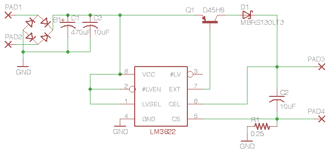
Fortunately, there are several integrated circuits available that are designed specifically to monitor the charging of Li-Ion cells. I went with the simplest one I could fine: the National Semiconductor LM3622, available from Digikey for $3 (or you can ask National for samples). The LM3622AM-4.1-ND takes anything from 4.5V up to 24V and puts out exactly 4.1V. It controls the current going into the cell by monitoring the cell's charge status and in its most basic configuration requires only 5 external components. National even has a handy application note about it, which suggests exactly what components and values to use for the highest efficiency.
Perfect! There's only one problem:

It only comes in a tiny 4.9mm x 3.9mm SOIC8 surface mount package. Having only ever soldered through hole components, I thought I'd hit a wall. But, it turns out that the SOIC8 is one of the larger SMD packages out there and that soldering with conventional techniques is not that bad (although I remained skeptical until I actually did it).
So, I designed the charging circuit, including a bridge rectifier, based on the design in National's application note. To make the schematic and layout the circuit board I used EagleCAD, a difficult to learn but ultimately useful FREE (for my needs at least) software package that can run on Mac OS 10. To make things even easier, Lady Ada has EagleCAD files on her site that include an LM3622 device used in her Wave Bubble, saving me the trouble of having to figure out how to configure custom devices in already hard-to-learn software.
Step 4: Test a prototype
I bought all the parts from Digikey, including an SOIC-8 to DIP-8 adapter (virtual robbery at $6.43 a piece) to facilitate the use of a prototyping breadboard.

Soldering the SOIC8 package to the DIP adapter proved to be easier than I thought. I was even drunk and shaky from too much coffee.
Using a regulated DC power source, I was able to get 4.09V over a range of input voltages and when connected to a discharged Li-Ion cell, the charging circuit drew about 180mA and took about 2 hours to drop the current to a couple hundred µA, indicating that the charge was complete. I tested a rectified AC source from the motor-crank assembly of a wind-up flashlight to roughly mimic the output of the dynohub (albeit with a much higher frequency) and the circuit worked fine. Success!
Now to see if the GH6 Dynohub could power the charger:

Even at low to moderate speeds, the GH6's output was good enough to power the circuit. Spinning the wheel as fast as I could made the voltage across the rectifier peak close to 20V, a little over 4V shy of the LM3622's maximum rated input. I doubt my wife will ever go that fast, even downhill in relatively flat Toronto.
Here is the complete parts list for the charger:
1 LM3622 IC
1 D45H8 transistor
1 MBRS130L diode
2 10 µF capacitor
1 0.22ohm resistor
1 1000 µF electrolytic capacitor
1 W02M 1.5A 200V bridge rectifier
1 CR123A 880mAh 3.6V Li-Ion battery
Step 5: Make a PCB
The charging circuit needs to be assembled into as small a package as possible to fit into the housing of the headlamp. Here's what I came up with:

With no mad PCB-routing skills, this is the best I could do for a single-sided design with large traces and pads suitable for DIY etching. Q1 is a large 10A power transistor and probably could have been swapped for a smaller SMD component such as the STN479 used in the design of the Wave Bubble. I decided to stick with the D45H8 suggested in National's application note, even if it was overkill. The final footprint of the PCB is a little less than 1.3" square. Download the EagleCAD project here.
Using a PDF (derived from the EPS output of EagleCAD's CAM processor), I made the etch-resist mask using the toner transfer method. This was considerably harder to master than advertised. After several attempts, I had a reasonable looking etch-resist pattern that still required a bit of touching up with a black Sharpie pen. I etched the board using ammonium persulphate (220g/L) which we have in the biochemistry lab where I work. Using a magnetic stirring hot plate to keep the the temperature at 60ºC and the solution in constant motion the board was nicely etched in less than 10 minutes.
A few minutes of soldering later, the circuit was complete!
 I got a little too excited after finishing it and soldered in test pins, making the connection of the battery and dynohub leads a little sloppy.
Here's the bottom of the board with the surface mount LM3622 and diode. This time I was sober and coffee-free.
Step 6: Connect to the dynamo
Now the whole thing needs to be connected to the dynamo and stuffed into the headlamp.
 All connected. On the upper right you can see a 6.8ohm 2W current limiting resistor connected in series with the rear light.
 Wrap it all up in electrical tape and stuff it in there. Plenty of room left over.
Now for the rear light. The LED won't fit into the wedge socket by itself so I cut out a small piece of PCB and soldered it to the leads to approximate a wedge base bulb.

 Fits snuggly in the socket. The bulb looks like it's a bit too long.
 But the lens fits!
How's it look in the dark?

 The rear light is super bright. Blinding, actually. Even brighter than the front, but using about half the current.
Final thoughts
Everything seems to work. The only problem I've had so far is that the battery wasn't fully charged when I installed it. The two lights discharge the battery faster than the dynamo can charge it, so on the first night out I wound up draining the battery completely, preventing the lights from staying on when stopped (the charging circuit seems to provide enough current to power both lights while the bike is in motion when the battery is dead). I expect a long ride during the day with the lights off should get it charged up sufficiently. That said, for long night rides this design is somewhat lacking. Under the conditions my wife is likely to ride, I suspect it will rarely be a problem.
Another potential design flaw is excessive battery charging time. Other charging circuits incorporate a timer so that after the battery is held at full-charge for a determined amount of time the circuit shuts off completely (I think). The LM3622 doesn't incorporate at timer; as long as the wheel is spinning the charging circuit is on. I think this is probably OK for the long term health of the battery because the LM3622 monitors the charge state and drops the current to a few µA when the battery is fully charged . If the bike was ridden for hours and hours with the lights off then there could be an issue with battery lifespan, but my wife's bike will never be taken out for more than an hour or so once or twice a week so I don't think it will be problem.
Finally, there is the issue of the dynamo's output exceeding the 24V maximum rating of the LM3622. This is an unlikely but not impossible scenario. I don't doubt that flying down a steep hill at top speed would probably blow the chip. A better design would incorporate voltage regulation.
Back to the drawing board...
13 comments:
This is really cool, and I'm working on a project to implement a similar battery charging circuit. Unfortunately, we're kinda noobs, and we're having a few problem. I dunno if you could possibly answer a few questions...?
1. .22 ohm resistor seems ridiculously low...and I'm having trouble finding one, does the circuit require that specifically? Would substituting with another low resistance resistor be a terrible idea?
2. Does the orientation of the transistor matter?
I think that's it for now. Thanks for any help you can provide.
well, i'm a total noob as well. the 0.22 ohm resistor value is important. something about setting the voltage or the current for the charging circuit (can't remember). a 0.25 ohm is used in some designs. i ordered the 0.22 ohm resistor online.
the transistor orientation is very important. the transistor controls the current charging the battery. it is essential to control that current to prevent overcharging.
hope that helps!
Fantastic. You make it look so easy. I thought there must be a reason there are no dynamos that serve as chargers. Perhaps it's merely because no one has bothered yet.
Have you made any progress recently?
For my GCSE in technology, I am currently designing and making a bicycle charging unit, to charge, say an iPod or a phone.
The hardest part that I have found, is building a circuit that first changes the voltage, so that it can charge the battery, and then to convert the power from the battery into the appropriate voltage output for a USB port (4.9v). I have found on another website a circuit board I could use, however it didn’t say how much voltage the circuit would take.
I was just wondering but would it matter if you changed the battery to a 4v or 4.5v battery?
Thanks for your help
J Naito
Does your battery go for longer before it needs recharging? I'm assuming yes? Also is pedalling noticably harder with your dynamo attached?
@jun: Not sure I understand your question. My circuit is designed specifically to charge 3.6V lithium ion batteries that have a strict voltage requirement of 4.1 volts. I don't think 4.1V would be suitable to charge a higher voltage battery.
@Dean: The battery is constantly being charged when the bicycle is in motion, even when the lights are off. During day riding the battery is charged. During night riding it isn't clear to me if the draw from the lights is greater than the draw of the charging battery - ie. does the charging circuit provide enough power for the lights without draining the battery.
There is no noticeable drag from the dynamo.
I'm about to build out one of these since one I purchased melted--do you have any design updates/suggestions after using it for a couple of years? Some of the parts aren't made any more, but I'll figure out the replacement numbers.
@Paul
Unfortunately, as you pointed out, the LM3622 isn't available anymore (at least not from Digikey). I did a quick search and found several other Lithium Ion charge management chips. Each will have its own application circuit, so you'd have to follow the suggested design in the datasheet rather than what I've posted here for the LM3622. The only other improvement I would make would be a proper load switch that disconnects the battery from the lights while you are riding with the lights on. This would prevent the battery from being drained while you're riding. I incorporated a switch like this in another circuit I'm working on which I will post soon.
First, I gotta say that I'm both amazed and pleased that there are others in the world trying to do what I am. Last year I bought a 1951 Raleigh Clubman. Recently I bought a "Sport Headlight", which is about 2/3 the size of the standard headlight, and a tail light. I want to run both these off the Dynohub, which I believe is ~2W total output. I put together a full wave rectifier with 4 Schottky diodes (1N5818) and 1 10F capacitor (381LX103M016J012) to take out the ripple. My trouble is that I only have 2W to play with and I want both a bright headlight and taillight. Both fixtures use E10 bases. For the headlight the regular bulbs from ledlight.com, such as the Short Round L.E.D. E10 Screw Base L.E.D. Light Bulb seem to work, but can you recommend a good taillamp bulb? Thanks, Mike
@NewLondonBiker
I would love to get a Clubman some day. They are very uncommon here in North America.
I'm working currently on a system that will hopefully pull more than 2W out of the GH-6 Dynohub (and other dynamos) at higher speeds. If it works I'll open source it and maybe even make a kit available.
wrt to bulbs, I'm slowly reaching the conclusion that an E10 Edison LED bulb retrofit isn't the best solution for the brightest LEDs. I'm trying out a few custom PCBs that will hopefully mount into the housings for a variety of vintage lamps.
This sounds exciting; especially if you'd offer this as a kit or at least a list of part numbers. What i don't know about electronics could fill volumes. My latest experiment is to use a Tektite LS365 in both the headlamp and tail lamp. That seems to work. I'm always looking for something better, though.
I don't know if anyone will ans me after this long time but I will try anyway..
I've been working on a air borne turbine. I've made a box kite that has been modified to carry a bottle dynamo. The dynamo is gonna work as a wind genaretor to produce power. I'm a noob at charging a battery with with a DC dynamo. So I've searched a lot and found this blog. My target is to charge batteries 4.1 v to max 12 v.. I will use a voltage regulator to control it. But the main problem is I've a very little knowledge about this kind of circuit board. So what kind of parts will I need to maintain the voltage and regulate as I need? I'll very grateful if u could suggest me or atleast give me path to follow.......
There's lots of info out there if you look for it. A good place to post a question would be somewhere like the bicycle lighting subforum of candlepowerforums.com or the projects forum over at allaboutcircuits.com. The first decision you need to make is what kind of batteries you want to charge. NiMH or Lithium or NiCd or lead acid. Once you've decided you can then look up what charging methods you need to use and get advice. Good luck!
Post a Comment